Using a Laser To Measure Vignetting On Binoculars and Telescopes
Version 1.3b1 of 21/2/2021-4:17 a.m.
Vignetting is an undesirable manufacturing defect on binoculars and telescopes,
which prevents the full utilization of the objective lens, as a light gathering device.
It tends to appear more often with binoculars and less often with telescopes, although
cheap telescopes suffer from it, too.
To determine if your binoculars or telescope are vignetted, you can use a simple
procedure, which will measure approximately the amount of vignette. To do that, you
will need:
The instrument to be tested for vignette.
Two stable, height-adjustable tripods.
A green laser pointer.
A white projection surface, screen or wall.
A couple of latex strings to immobilize the laser on the second tripod.
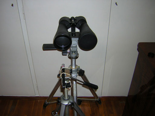
Here are some photos, which describe the author's setup, for testing vignette on his
11x80 Chinon binoculars:
Binoculars with optical axis normal to wall surface and green laser centered against
binocular objective
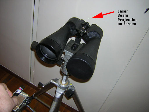
Laser moving UP towards the objective edge
Laser trace shown on the wall
The author now describes a process of measuring on-axis vignette, for a pair of
binoculars:
If your main mount has balance bubbles (like the author's professional Chinon
tripod), set your binoculars on it, and adjust its altazimuth mount until all bubbles
are in the middle.
Adjust the binocular's tripod position until the binocular's projected image is
perpendicular to an available vertical white wall or screen. The altazimuth levers
may need to be adjusted further, until the optical axis of the binoculars is exactly
normal to the projected surface (see below).
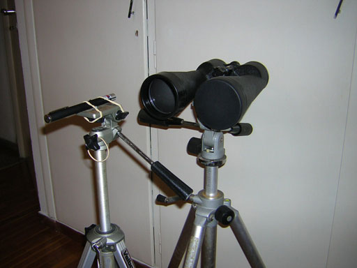
Position the laser so its beam is parallel to the optical axis of the binocular,
as best as you can, and center its beam against the binocular objective. This may be
a little tricky, because with cheap green lasers the beam axis is not always parallel
to the laser stylus.
Once you position the laser on the second tripod so its beam is parallel to the
binocular optical axis, rotate the tripod height-adjustment crank, so as to force the
laser beam to move UP against the vertical diameter of the objective, until the beam
reaches near the objective edge and until you notice extinction of the projected
laser beam against the wall. Measure the distance V1 between the laser beam spot
against the objective and the objective's edge.
Then, rotate the tripod height-adjustment crank, so as to force the laser beam to
move DOWN against the vertical diameter of the objective, until the beam reaches near
the objective edge and until you notice extinction of the projected laser beam
against the wall. Measure the distance V2 between the laser beam spot against the
objective and the objective's edge.
If the two distances you measured are not equal, then, either the laser beam is
not exactly parallel to the optical axis of the binocular, or the binocular's optical
axis is not exactly normal to the projection screen. In such a case, go back and
repeat steps 2 and 3.
Repeat steps 4 and 5, until the two distances V1 and V2 you measure in these
steps are equal.
If V1=V2=0, your binocular has no vignette, so you can stop here.
If V1=V2=V>0 your binocular is vignetted, and the situation is shown on the
following diagram:
Optics diagram for a binocular with vignette
If the binocular's objective diameter is D, then because of the vignette V, your
binocular's effective diameter is really Deff=D-2*V. In the case of
the author's Chinon 11x80 binoculars, D=80mm and V=4mm, hence the effective diameter
of the Chinon 11x80 binoculars is Deff=80-2*4=72mm.
Since light gathering power varies proportionately to the area of the objective,
your light gathering power now is (Deff/D)2 of what it would be
if the full diameter was utilized. Because of vignette then, the author's binoculars
have (72/80)2~81% of the light gathering power of what the binoculars
would have had if the full objective lens was utilized.
The steps for measuring off-axis vignetting at angle a>0, are exactly the same as
those above, with the inclusion of step 3:
Rotate the binos against the laser beam axis, to a fixed angle a>0.
The situation is similar for telescopes, but the diagram differs, because there is
no image erecting system, so the image reverses itself at the objective's focal plane.
In this case, the diagram is shown below:
Optics diagram for a telescope with vignette
Note that whether a scope suffers from vignette or not, the projected length of the
trace of the laser beam on the screen/wall as the laser beam moves from the upper to
the lower part of the objective lens, will always equal the Exit Pupil of the
instrument, EP.