

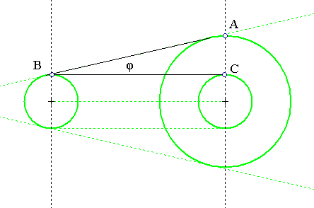
Typical laser beams diverge at large distances. The beam divergence, is defined to be the angle φ on the figure below.
One can measure the divergence directly, using two photographs of the laser beam: One at a small distance and a second at a relatively large distance. Follow two pairs of photographs for two typical laser beams, at a reference distance on the left and at a distance of 9.6m on the right.
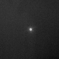
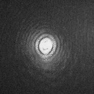
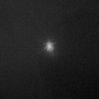
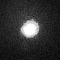
For the first pair, according to the first figure and considering the width of the beam up to the first diffraction ring, the divergence @9.6m, would be such that:
tan(φ)=AC/BC. With BC = 9.6m = 9600mm. For the first pair, the beam on the left side has a diameter of ~3mm, and on the right a diameter of ~12mm. Therefore the divergence of the red laser diode @9.6m is such that:
tan(φ)=(12/2-3/2)/9600 => φ ~ 0.000468749965 rad ~ 4.6 millirad@9.6m.
For the second pair, the beam on the left side has a diameter of ~2mm, and on the right a diameter of ~11mm. Therefore the divergence of the green laser diode @9.6m is such that:
tan(φ)=(11/2-2/2)/9600 => φ ~ 0.0005208332862 rad ~ 5.2 millirad@9.6m.
Now let's measure the beam distribution of the second beam. For this, we slice the beam target with Iris at angles α(k)=2*k*π/n, with n=8, and k in {0,1,2,3,..7}. Because the slices are symmetric past k=3, it suffices to run k in {0,1,2,3}.
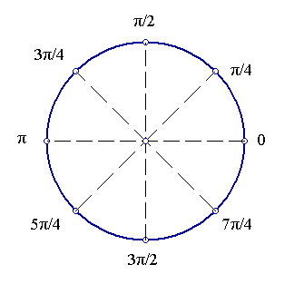
Follow the distributions:
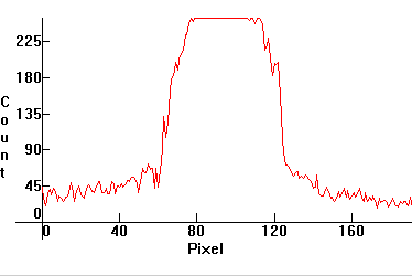
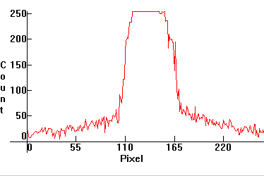
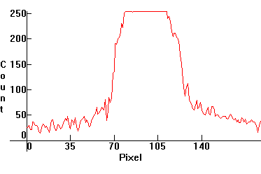
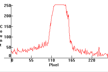
If we pick the first distribution, we can see that its profile is almost Gaussian G(x,σ,μ), but not quite:
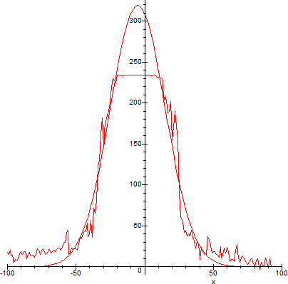
Because the slices are not symmetric, the green laser beam is then necessarily astigmatic, with respect to at least one angle α(k).