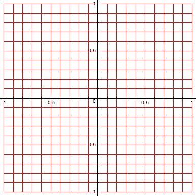
The following Maple code builds a 10x10 grid of the complex plane z:
> with(plots):
> f:=(rho,theta)->rho*exp(I*theta);
> nmax:=10; #subdivision for complex plane grid
> us:=z->z/nmax; #normalize to unit square grid
> w:=z->us(z); #function to be mapped into w-plane (here w=z=id)
> for n from -nmax to nmax do
> hor[n]:=complexplot(w(f(rho,0)+n*I),rho=-nmax..nmax,color=red); #horizontal
lines
> od:
> h:={}:
> for n from -nmax to nmax do
> h:=h union {hor[n]};
> od:
> for n from -nmax to nmax do
> ver[n]:=complexplot(w(f(rho,Pi/2)+n),rho=-nmax..nmax,color=red); #vertical
lines
> od:
> v:={}:
> for n from -nmax to nmax do
> v:=v union {ver[n]};
> od:
> grid:=h union v:
> display(grid);
Here's the resulting grid:

By interjecting a suitable function in the line, for example:
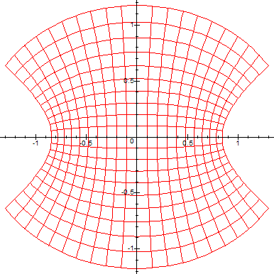
> w:=z->cos(us(z)); #function to be mapped into w-plane (in this case
"cos"),
we can visualize how the function transforms the z-plane to w-plane. Here are some
examples of running the above code with different complex functions[1][2]:
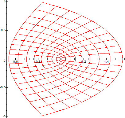
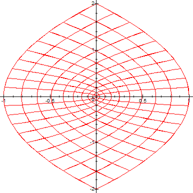
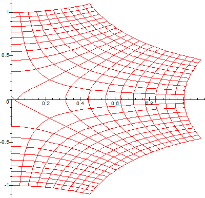
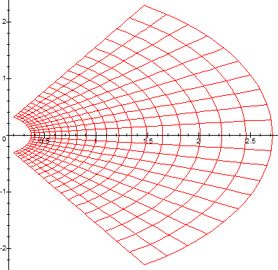
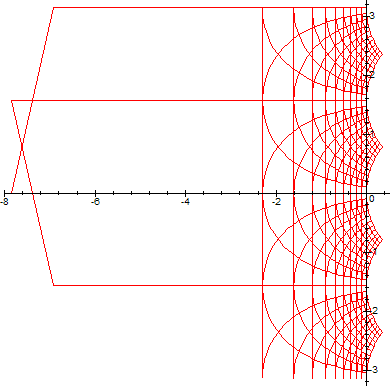
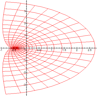
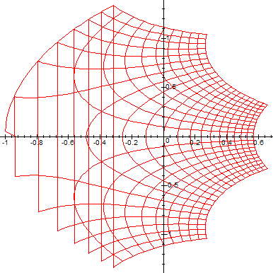
(Note that the range of W is delimited on the left by the curve -y*cot(y)+y*I. For more details on this, consult this article).